
Part 1A of a series for plant and design engineers on Dean hot-service pumps.
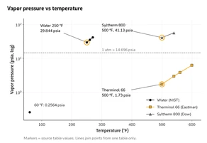
Water at 250 °F cannot be held liquid at atmospheric pressure. Heat transfer fluids at 500 °F split both ways, and the shape of each fluid's vapor pressure curve decides whether the loop needs a nitrogen blanket or real pressurization. This part sets the tank pressure against flashing, works the Therminol 66 and Syltherm 800 cases, and sizes the expansion tank. Every calculation is shown with its inputs and units.
Which Dean pump for which fluid. The Dean RWA is the hot-water pump, for hot water and glycols [17, PDF p. 4]. See the Dean RWA Series and the Dean RWA4166. The Dean RA is for heat transfer oils only. See the Dean RA Series and the Dean RA3146. Both series are air-cooled. Both share the same hydraulic curves for a given size, rated on ambient-temperature water. The split between them is not cooling. It is the seal package, the elastomers, and the vapor eliminator fitted to the RWA. Part 1B tabulates the differences.
1. Vapor pressure basics
1.1 Data conventions
- Water properties are from the NIST Chemistry WebBook saturation tables [1] at 60, 250, 260 and 270 °F. CoolProp 8.0.0 (IAPWS-95) [2] reproduces them to the digits shown.
- The specific gravity (SG) reference is saturated water at 60 °F, 62.3637 lb/ft³ [1].
- Therminol 66 data are from Eastman Technical Bulletin TF-8695 [3].
- Syltherm 800 data are from Dow's SYLTHERM 800 Heat Transfer Fluid product technical data brochure [4]. Its SI table matches the separate Dow technical data sheet [5] at every common temperature checked.
- Anything labeled example assumption is a system input chosen for illustration. It is not a property value and not a recommendation for your plant.
1.2 Properties at the design points
Water at 250 °F (RWA service) [1]:
| Property | Value |
|---|---|
| Pv at 250 °F | 29.8440 psia |
| Pv at 260 °F / 270 °F (overshoot checks) | 35.4473 psia / 41.8777 psia |
| Density ρ | 58.8202 lb/ft³ |
| SG | 58.8202 / 62.3637 = 0.9432 |
| Dynamic viscosity μ | 0.229755 cP |
| Kinematic viscosity ν | 0.244 cSt (calculated) |
Thermal fluids at 500 °F / 260 °C (RA service):
| Property at 500 °F | Therminol 66 [3] | Syltherm 800 [4] |
|---|---|---|
| Vapor pressure | 1.73 psia (12.0 kPa) | 41.13 psia (283.6 kPa) |
| Density | 52.5 lb/ft³ (7.01 lb/gal; 840 kg/m³) | 44.62 lb/ft³ (713.96 kg/m³) |
| SG (ref. water 60 °F, 62.3637 lb/ft³) | 0.842 | 0.7155 |
| Dynamic viscosity | 1.28 lb/(ft·h) = 0.529 cP | 0.63 cP |
| Kinematic viscosity | 0.629 cSt | 0.88 cSt (calculated, μ/ρ) |
| Specific heat | 0.578 Btu/(lb·°F) (2.42 kJ/kg·K) | 0.482 Btu/(lb·°F) (2.018 kJ/kg·K) |
| Thermal conductivity | 0.0574 Btu/(ft·h·°F) (0.0993 W/m·K) | 0.0519 Btu/(h·ft·°F) (0.0899 W/m·K) |
| Normal boiling point / character | 678 °F (359 °C) [3] | No distinct boiling point; vapor pressure drifts up with time at temperature [4] |
| Max recommended bulk temperature | 650 °F (345 °C, as printed) [3] | 750 °F (400 °C) [6] |
SG and the Syltherm kinematic viscosity are calculated. Everything else is copied from the vendor tables, with SI values from each vendor's own SI table. Eastman's English table lists viscosity in lb/(ft·h) followed by cSt. Do not read the first column as cSt.
Small rounding differences are as printed. Eastman rounds density and lb/gal independently (52.5/7.4805 = 7.018). Dow's English and SI Syltherm densities differ by 0.1 % because 260 °C is only approximately 500 °F.
1.3 The shape of the curve sets the system architecture
The three fluids behave very differently at their operating temperatures:
- Water at 250 °F: Pv is about twice atmospheric. The loop must be pressurized.
- Therminol 66 at 500 °F: 178 °F below its normal boiling point. Pv is 1.73 psia, below atmospheric. A blanket is enough.
- Syltherm 800 at 500 °F: Pv is 41.13 psia, almost three atmospheres (2.80 atm). The loop must be pressurized.
Steepness matters as much as level. Over 500 → 540 °F, Syltherm 800 rises from 41.13 to 56.85 psia, which is +15.7 psi, or about 51 ft at 500 °F density. Therminol 66 rises only from 1.73 to 2.97 psia, which is +1.24 psi, or about 3.4 ft [3][4]. Water from 250 to 270 °F rises 12.03 psi (Section 3.2).
2. Converting pressure to head
Every pressure in this part is converted to feet of liquid at the pumping temperature.
Pressure to head, in US units:
Here 2.309 = 144/62.3637, and SG is referenced to 62.3637 lb/ft³ (saturated water at 60 °F). With SG = ρ/62.3637 the two forms are identical: 2.309/SG ≡ 144/ρ. Two rules apply throughout:
- Use absolute pressure for both hp and hvp.
- Use the density at the pumping temperature.
For water at 250 °F:
3. Anti-flash pressurization for the RWA hot-water loop
3.1 Minimum tank pressure
Flashing begins wherever local static pressure comes closest to local saturation pressure. With the tank tied in at the pump suction (the point of no pressure change), the candidates are:
- The system high point, which governs when the pump is off.
- The pump suction, covered by NPSHa vs NPSHr (see Part 1B).
- The point of maximum temperature downstream of the heater.
Margin basis. High-temperature-water design guidance sets system pressure at least 25 psi above the saturation pressure at the maximum water temperature, to prevent flashing and cavitation [7][8][9]. This is design guidance from secondary sources, not a code requirement.
Example assumptions: high point 60 ft above the tank connection; maximum water temperature 250 °F; tank tied in at the pump suction.
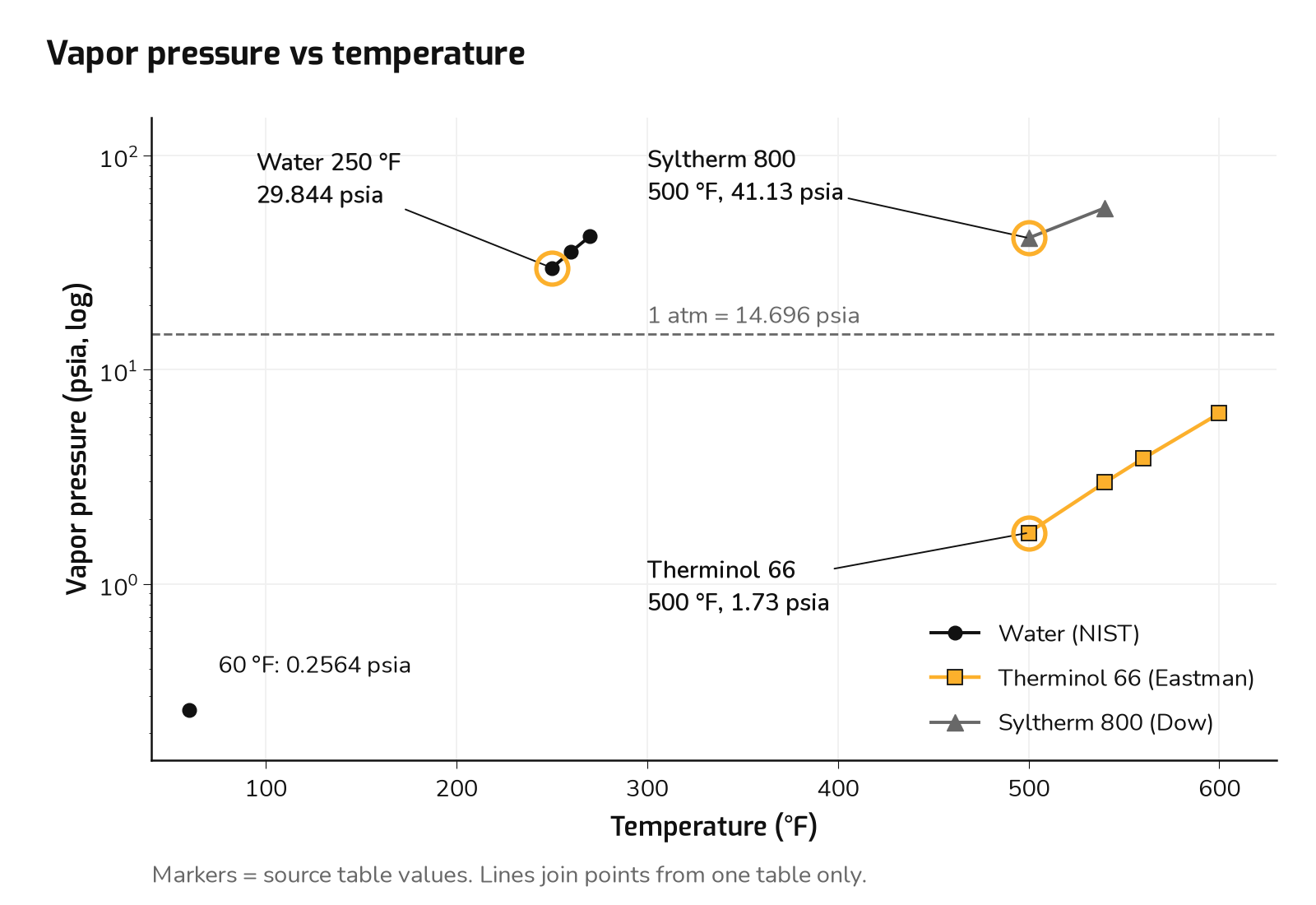
(a) Minimum pressure at the high point:
(b) High-point static correction, psi = ft / (2.309/SG):
(c) Minimum tank pressure:
The pump-off case governs. With the pump running and the high point on the return side, friction only raises the high-point pressure, so ignoring it is conservative.
| Basis | Tank pressure | Governs? |
|---|---|---|
| NPSH only, 13.3 ft target at 250 °F | 18.5 psig | No |
| NPSH only, including 260 °F overshoot | 24.1 psig | No |
| Anti-flash, Pv + 25 psi, no high point | 40.15 psig | No (ignores the high point) |
| Anti-flash, Pv + 25 psi at a 60 ft high point | 64.66 psig (79.35 psia) | Yes |
The two NPSH-only rows are derived in Part 1B, Section 4.3. They are shown here to confirm that flashing, not NPSH, sets the tank pressure.
Temperature gradient in the riser. The isothermal 250 °F column is the design case. A column that cools toward the top is denser, so the high point sits at a slightly lower pressure (up to 0.9 psi lower here). Saturation pressure falls much faster, though, and the minimum margin moves down to the 250 °F water at the tank connection (49.5 psi). So hot water reaching the high point, at 25.0 psi margin, is what governs.
| Column, bottom → top | Static head (psi) | Pressure at top (psia) | Psat at top (psia) | Margin at top (psi) | Minimum margin (location) |
|---|---|---|---|---|---|
| 250 → 250 °F (isothermal, design basis) | 24.51 | 54.84 | 29.84 | 25.0 | 25.0 psi (high point) |
| 250 → 150 °F | 25.03 | 54.32 | 3.72 | 50.6 | 49.5 psi (tank connection) |
| 250 → 60 °F | 25.39 | 53.96 | 0.26 | 53.7 | 49.5 psi (tank connection) |
Basis: temperature varies linearly with elevation. dP/dz = −ρ(T)/144 is integrated numerically using saturated-liquid water densities from CoolProp 8.0.0 (IAPWS-95) [2], which match NIST [1] at 60 °F (62.3637 lb/ft³), 250 °F (58.8202 lb/ft³) and 150 °F (61.19 lb/ft³). Margin is the local pressure minus Psat at the local temperature, checked at every elevation. Treating density as linear in temperature changes the top pressure by at most 0.14 psi.
Overshoot. With the tank held at 79.35 psia, a 260 °F excursion cuts the high-point margin from 25 psi to 19.4 psi. Section 3.2 covers re-basing for a higher high-limit.
3.2 Design to the maximum reachable temperature
Set tank pressure from the temperature the heater high-limit allows, not from the setpoint. With the water tank pressure unchanged [1]:
| Max temperature | Pv (psia) | Margin lost (psi) | Margin lost (ft, at 250 °F density) |
|---|---|---|---|
| 250 °F | 29.8440 | 0 | 0 |
| 260 °F | 35.4473 | 5.60 | 13.7 |
| 270 °F | 41.8777 | 12.03 | 29.5 |
A 20 °F overshoot takes nearly half of the 25 psi margin. If the high-limit allows 270 °F, base the minimum on 41.88 psia:
4. The N₂ blanket: Therminol 66 in RA service
Therminol 66 at 500 °F sits 178 °F below its normal boiling point, with a vapor pressure of 1.73 psia. Part 1B, Section 5.2 works its NPSHa: 40.6 ft at a 0 psig blanket against the 10 ft printed NPSHr label. The NPSH margin target is met at 4.74 psia (≈ −10.0 psig).
At 500 °F, any non-negative blanket pressure meets the NPSH target with wide margin. The nitrogen blanket exists to exclude air and moisture and to control oxidation, not for NPSH. Dean notes that oil makers "will recommend that a nitrogen gas blanket be maintained on the expansion tank of the system" [16, p. 16]. A slight positive blanket also keeps air out. The setpoint is a heater-OEM and fluid-supplier decision.
5. Syltherm 800 at 500 °F needs a pressurized tank
Example inputs from Part 1B. Same RA3146 2x3x8.5 at 150 gpm. Liquid level hz = 6.0 ft above the pump centerline (example assumption). Computed clean-line suction friction 0.96 ft. NPSHr is the printed 10 ft label. The NPSH margin target is 13.3 ft, the larger of 1.1 × NPSHr or NPSHr + 3.3 ft (Part 1B, Section 2.5).
Conversion factor and friction. SG = 0.7155 (44.62/62.3637 = 0.71548):
At a low blanket, the fluid boils. With a 17.0 psia blanket (about 2.3 psig), hz = 6.0 ft and hf = 0.96 ft:
| Tank (psig) | NPSHa (ft) |
|---|---|
| 0 | −80.3 |
| 10 | −48.0 |
| 20 | −15.7 |
| 25 | +0.4 |
Like the RWA water case, a Syltherm 800 loop at 500 °F must be pressurized. Dow states that where tank elevation alone cannot meet the pump's NPSH, "NPSH requirements can be met by increasing the amount of the blanket gas (usually nitrogen) in the vapor space of the expansion tank ... However, the additional system pressure created by the nitrogen should be accounted for during the system design" [4, p. 6].
NPSH alone is not a sufficient basis. On the NPSH margin target alone (13.3 ft against the 10 ft label):
That is only 43.69 − 41.13 = 2.6 psi over the tabulated vapor pressure. It allows nothing for the rise in vapor pressure as the fluid ages:
"As supplied, SYLTHERM 800 heat transfer fluid exhibits a low vapor pressure. With time at high temperatures, the previously described rearrangement reaction results in a gradually rising vapor pressure. Ultimately, the silicone components reach an equilibrium composition and exhibit an equilibrium vapor pressure. ... In practice, operating pressures in the expansion tank are often higher than values indicated by the curve due to the additive effect of other gases such as the nitrogen blanket gas or noncondensible by-products of operation." Dow Form 176-01435, "Equilibrium and Operating Pressures", p. 5 [4]
Dow's margin guidance for the expansion-tank regulator:
"the back pressure regulator setting on the expansion tank will control the pressure at the entrance to the pump. The regulator set point should be a minimum of 10 to 15 psi (0.7 to 1.0 bar) above the vapor pressure corresponding to the fluid temperature in the expansion tank." Dow Form 176-01435, p. 6 [4]
Example assumption: N₂ blanket at Pv + 25 psi. This is the same margin basis as the water case (Section 3.1), applied here as our design choice. It is above Dow's stated 10–15 psi minimum. Dow recommends a flow-through expansion tank at the system high point, which "allows the expansion tank to be the lowest pressure point in the system" [4, p. 5]. With that layout no high-point static correction is added. The tank is conservatively taken at 500 °F.
| Basis | Tank pressure | NPSHa (ft) | Ratio to 10 ft |
|---|---|---|---|
| NPSH target only (not recommended) | 43.69 psia / 29.0 psig | 13.3 | 1.33 |
| Dow minimum, Pv + 10 psi | 51.13 psia / 36.4 psig | 37.3 | 3.73 |
| Dow minimum, Pv + 15 psi | 56.13 psia / 41.4 psig | 53.4 | 5.34 |
| Example design: Pv + 25 psi | 66.13 psia / 51.4 psig | 85.7 | 8.57 |
Aged-fluid vapor pressure. As supplied, Syltherm 800 has a low vapor pressure. With time at temperature it rises, and over "usually a matter of months" it reaches an equilibrium value [4, p. 5]. Dow states that its Figures 7 and 8 "show the ultimate equilibrium silicone vapor pressure that SYLTHERM 800 heat transfer fluid should generate over a period of time at the indicated temperatures," and that all system temperatures and pressures "should fall on or above the curved line" [4, p. 5]. Read graphically at 500 °F, Figure 7 (Dow Form 176-01435, p. 18, Fig. 7 [4]) gives about 40 psia, a log-scale estimate good to a few psi. That agrees with the Table 4 value of 41.13 psia, so the tabulated figure used here is effectively Dow's long-term equilibrium value, not a fresh-fluid number. Against it, the 66.13 psia blanket leaves 25.0 psi, or about 81 ft.
The brochure gives no data on vapor pressure versus elapsed time, and nothing above the equilibrium curve. Dow's warning that tank pressures run higher than the curve gives no quantity. Track it by fluid analysis. Dow offers a sampling service and recommends a sample at least annually (Dow Form 176-01435, p. 11 [4]). If the aged value exceeds about 56 psia at 500 °F, raise the setting to keep 10–15 psi over it.
RA3146 limits. Pump suction is 51.43 + (6.0 − 0.96)/3.2271 = 53.0 psig, under the 100 psig maximum suction. Discharge is 53.0 + 230/3.2271 = 124.3 psig, under 350 psig. The gap between the 51.4 psig setting and the 100 psig suction limit is what remains for the expansion-tank pressure swing and the relief setting.
6. Three fluids, three architectures
| Fluid at duty | Tank pressure basis | Example setting |
|---|---|---|
| Water, 250 °F (RWA) | Anti-flash: Pv + 25 psi at the 60 ft high point | 79.35 psia / 64.66 psig minimum |
| Therminol 66, 500 °F (RA) | Blanket for air and moisture exclusion; NPSH met at any non-negative pressure | 0 psig in the example; setpoint per heater OEM and fluid supplier |
| Syltherm 800, 500 °F (RA) | Pv + 25 psi at a high-point flow-through tank (Dow minimum Pv + 10–15 psi) | 66.13 psia / 51.4 psig |
The +25 psi margin is a design choice drawn from high-temperature-water guidance [7][8][9]. It is not a code requirement. Applying it to Syltherm 800 is our choice. Dow's own stated minimum is 10–15 psi over vapor pressure.
7. Expansion tank sizing
7.1 Volumetric expansion
At constant mass:
Pipe and vessel growth is approximately 3αΔT.
7.2 RWA service: closed hot-water loop, 60 → 250 °F
The ASHRAE Handbook closed-tank equations [10] are as follows. For a plain steel tank (air/water interface):
For a diaphragm or bladder tank:
All pressures are absolute at the tank. α is taken as 6.5 × 10⁻⁶ /°F for steel, as used in the ASHRAE handbook example [13].
The diaphragm-tank equation matches manufacturer sizing literature. Taco's catalog uses the same numerator, [(v2/v1) − 1] − 3αΔt, and an absolute-pressure acceptance factor 1 − P1/P2 [11]. AMTROL gives the same acceptance factor as the ASHRAE diaphragm-tank form [12]. The plain-steel (air-cushion) form is as reproduced in [10][13], consistent with ASHRAE Handbook—HVAC Systems and Equipment, Ch. 13. The steel α of 6.5×10⁻⁶ /°F is the value used in the ASHRAE handbook example as reproduced in [13].
Example assumptions:
| Input | Value |
|---|---|
| System volume Vs | 500 gal |
| Cold fill pressure P1 | 85.0 psia (70.3 psig), above the 79.35 psia minimum |
| Maximum pressure at the tank P2 | 125.0 psia (110.3 psig), kept below the relief setting and far below the RWA4166's 260 psig suction limit and 450 psig casing rating |
| Atmospheric Pa | 14.696 psia |
| Density at 60 °F / 250 °F | 62.3637 / 58.8202 lb/ft³ [1] |
| Step | Calculation | Result |
|---|---|---|
| Fluid expansion | 62.3637/58.8202 − 1 | 0.06024 |
| Pipe growth | 3 × 6.5e-6 × 190 | 0.00371 |
| Net expanded volume | 500 × 0.05654 | 28.3 gal |
| Bladder tank | 28.3 / (1 − 85/125 = 0.320) | 88.3 gal |
| Plain-steel tank | 28.3 / (14.696/85 − 14.696/125 = 0.05533) | 511 gal |
The plain tank's acceptance factor is small because of the fill pressure needed to keep the water liquid. That is why pressurized hot-water plants use bladder tanks or nitrogen pressurization with level-controlled gas makeup [7][9].
7.3 RA service: thermal fluid loops, 80 → 500 °F
Example assumptions: loop volume 1,000 gal at 80 °F. The tank operates at roughly constant blanket pressure, so there is no compression term. The tank is sized to be about 25 % full cold and no more than 75 % full hot. This band is a common working convention, not a cited standard. Confirm it against the heater OEM's or fluid supplier's design guide.
| Step | Therminol 66 [3] | Syltherm 800 [4] |
|---|---|---|
| ρ at 80 °F | 62.7 lb/ft³ | 58.06 lb/ft³ |
| ρ at 500 °F | 52.5 lb/ft³ | 44.62 lb/ft³ |
| ΔV/V₁ = ρ₈₀/ρ₅₀₀ − 1 | 0.1943 | 0.3012 |
| ΔV, 1,000 gal loop | 194 gal | 301 gal |
| Steel credit 3αΔT × V (ΔT = 420 °F) | 8.2 gal | 8.2 gal |
| Tank, 50 % usable band (no credit) | 389 gal | 602 gal |
Over the same temperature range, Syltherm 800 expands about 55 % more than Therminol 66 (ratio 1.55). It expands 5.0 times as much as water does over 60 → 250 °F; Therminol 66 expands 3.2 times as much.
For a Syltherm loop at 500 °F, the tank is also a pressure vessel holding about 51.4 psig of blanket, before any compression rise. Size its volume and pressure rating together. The blanket compresses as the fluid expands into the tank. That case needs a gas-law check like the plain-tank equation above, or a blanket held by pressure regulator and relief.
8. Fluid properties and pump selection
| Condition | ρ (lb/ft³) | SG | ν (cSt) | Pv (psia) | Source |
|---|---|---|---|---|---|
| Water, 60 °F | 62.3637 | 1.000 | 1.12 | 0.2564 | [1] |
| Water, 250 °F (RWA) | 58.8202 | 0.9432 | 0.244 | 29.844 | [1] |
| Therminol 66, 60 °F | 63.1 | 1.012 | 186 | — | [3] |
| Therminol 66, 500 °F (RA) | 52.5 | 0.842 | 0.629 | 1.73 | [3] |
| Syltherm 800, 60 °F | 58.69 | 0.941 | 11.6 (calc. from 10.9 cP) | 0.0 | [4] |
| Syltherm 800, 500 °F (RA) | 44.62 | 0.7155 | 0.88 (calc. from 0.63 cP) | 41.13 | [4] |
Density and SG set power and pressure.
At the same flow and head, a 60 °F cold start draws more power than the 500 °F duty: 1.20 times as much for Therminol 66 (63.1/52.5) and 1.32 times as much for Syltherm 800 (58.69/44.62). Size the RA motor for cold circulation, or control start-up flow. On the RWA side, water at 250 °F (SG 0.9432) needs about 5.7 % less power than cold water.
Viscosity and the 70 SSU curve limit. Dean curves apply to liquids of 70 SSU or less [15]. Engineering ToolBox's ASTM D2161-based table gives 10 cSt = 58.8 SSU and 15 cSt = 77.4 SSU, so 70 SSU ≈ 13 cSt [14].
- At duty, every fluid here is thinner than cold water (0.24–0.88 cSt), so water performance curves apply. Therminol 66 at 0.629 cSt is below 2 cSt (32.6 SSU), at the bottom of the Saybolt scale.
- At cold start, Therminol 66 is 186 cSt at 60 °F, 70.8 cSt at 80 °F (about 330 SSU) and 11.7 cSt at 140 °F (about 64 SSU) [3]. The water curve is therefore not valid below roughly 130–140 °F. Treat cold circulation as a viscous-correction case under ANSI/HI 9.6.7: correct head, flow and efficiency, and recompute suction friction. Size the motor for it, or interlock until the fluid is warm.
- Syltherm 800 stays much thinner cold: 11.6 cSt at 60 °F.
Vapor pressure sets NPSH and pressurization. Therminol 66 at 500 °F needs only a blanket. Syltherm 800 at 500 °F and water at 250 °F both need real pressurization plus margin. Both are very sensitive to temperature overshoot (Sections 5 and 3.2).
Use the hot density in the NPSH conversion. Converting a psi margin with cold density overstates the head available.
9. Takeaways
- Match the pump to the fluid. Hot water and glycols: Dean RWA. Heat transfer oils: Dean RA. Use the shared R-series curve for the size.
- Get properties at the maximum reachable temperature, set by the heater high-limit, not the setpoint: Pv, ρ, μ.
- For water and pressurized fluids, set tank pressure against flashing first. Example basis: Pv + 25 psi at the system high point, plus the static correction. NPSH then becomes a check. The 25 psi is a design choice, not a code requirement.
- For Syltherm 800, use the aged (equilibrium) vapor pressure. Keep at least Dow's 10–15 psi over it, and verify by fluid analysis at least annually.
- Check pump limits: maximum suction pressure (RWA4166 260 psig, RA3146 100 psig), working pressure at temperature (RWA4166 450 psig to 400 °F, RA3146 350 psig to 650 °F), and seal-chamber pressure (RWA: suction + 0.06 × developed head).
- Size the expansion tank from the density ratio, with the fill and maximum pressures set inside the relief setting and pump limits.
- Check cold start: viscosity correction above 70 SSU and motor power at cold SG.
For NPSH checks, pressurization and Dean RA or RWA selection, use HydroSuite Pro, or call 888-341-7085 / email sales@pumpresource.us.
Continue with Part 1B: Part 1B: NPSH, cavitation and thermal growth covers NPSHa, NPSH3 and the HI 9.6.1 margin, the worked NPSHa examples, suction piping, cavitation and flashing damage, and casing thermal growth.
References
Standards and public data
- NIST Chemistry WebBook, SRD 69, Thermophysical Properties of Fluid Systems, water saturation tables. 250–270 °F: https://webbook.nist.gov/cgi/fluid.cgi?Action=Data&Wide=on&ID=C7732185&Type=SatP&Digits=6&THigh=270&TLow=250&TInc=10&RefState=DEF&TUnit=F&PUnit=psia&DUnit=lbm%2Fft3&HUnit=Btu%2Flbm&WUnit=ft%2Fs&VisUnit=cP&STUnit=lb%2Fin ; 60 °F: https://webbook.nist.gov/cgi/fluid.cgi?Action=Data&Wide=on&ID=C7732185&Type=SatP&Digits=6&THigh=60&TLow=60&TInc=10&RefState=DEF&TUnit=F&PUnit=psia&DUnit=lbm%2Fft3&HUnit=Btu%2Flbm&WUnit=ft%2Fs&VisUnit=cP&STUnit=lb%2Fin
- CoolProp 8.0.0 (IAPWS-95 water); Bell et al., Ind. Eng. Chem. Res. 53 (2014). http://www.coolprop.org/
- Eastman, Therminol 66 Heat Transfer Fluid, Technical Bulletin TF-8695, liquid property tables: https://www.eastman.com/content/dam/eastman/corporate/en/literature/t/tf8695a.pdf ; datasheet: https://productcatalog.eastman.com/tds/ProdDatasheet.aspx?pn=Therminol+66+heat+transfer+fluid&product=71093438
- Dow, SYLTHERM 800 Heat Transfer Fluid: Product Technical Data, Form No. 176-01435-1097 (Oct. 1997), Table 4/5 saturated liquid properties and design sections; Fig. 7 on printed p. 18; fluid analysis and annual sampling on printed p. 11 (distributor-hosted copy): https://cms.chempoint.com/getmedia/ca6e00a4-1e13-4412-b5ce-d58e04a1562f/Syltherm800Brochure.pdf.aspx
- Dow, SYLTHERM 800 Silicone Heat Transfer Fluid product information, Form No. 176-01469-1101 (Nov. 2001) (copy): https://www.npl.washington.edu/TRIMS/sites/sand.npl.washington.edu.TRIMS/files/manuals-documentation/syltherm-800-technical-data-sheet.pdf
- Dow, SYLTHERM 800 Stabilized Heat Transfer Fluid: https://www.dow.com/en-us/pdp.syltherm-800-stabilized-heat-transfer-fluid.39260z.html
- J. P. Guyer, An Introduction to High Temperature Water Heating Plants, PDH Online M380: https://pdhonline.com/courses/m380/m380content.pdf
- HPAC Engineering, "Design of a High-Temperature-Hot-Water-Plant Expansion": https://www.hpac.com/heating/article/20928647/design-of-a-high-temperature-hot-water-plant-expansion
- Consulting-Specifying Engineer, "Specifying high-temperature hot-water boilers and systems": https://www.csemag.com/specifying-high-temperature-hot-water-boilers-and-systems/
- ASHRAE, ASHRAE Handbook—HVAC Systems and Equipment, Ch. 13 "Hydronic Heating and Cooling" (2020 ed.; Ch. 12 in 2008 and earlier). Chapter listing: https://webstore.ansi.org/preview-pages/ASHRAE/preview_2020+ASHRAE+Handbook+(HVAC+Sys+Eq+(SI).pdf . Equations as written here were taken from secondary reproductions: S. Taylor, "Expansion Tank Sizing Formulas," https://hvac-eng.com/expansion-tank-sizing-formulas/ ; EngProGuides, https://www.engproguides.com/expansion-tank-hot-water-design-guide.pdf
- Taco, Flow-Through Expansion Tanks catalog 400-5.2, p. 3, Example 1, "Sizing of a Captive Air Expansion Tank": https://www.tacocomfort.com/documents/FileLibrary/Flow-Through-Expansion-Tanks_Catalog_400-5.2.pdf
- AMTROL, Sizing the EXTROL, form 9003-036 (03/19), ASHRAE Formula Method and acceptance factors: http://www.amtrol.com/wp-content/uploads/2019/06/9003-036-03_19-EXTROL-Sizing.pdf
- Reproduction of the ASHRAE 2000 HVAC Systems & Equipment Ch. 12 Example 1 (steel α = 6.5×10⁻⁶ /°F): https://pdfcoffee.com/download/expansion-tank-sizing-calculation-hydronic-system-4-pdf-free.html
- Engineering ToolBox, Viscosity Converter (cSt–SSU, ASTM D2161 basis): https://www.engineeringtoolbox.com/viscosity-converter-d_413.html
Dean literature
- Met-Pro / Dean Pump, Dean Pump Series RA data pak: spec page p. 2; dimension drawing RA-1003 (RA-3146 with shaft fan), PDF p. 6; curve sheets pp. 10–22.
- Tusk Industrial, Dean RA Series Installation, Operation and Maintenance Manual, document TUSK-IOM-DEAN-RA-001 v1.0 (distributor-hosted copy, file Dean-RA-Series-IOM.pdf; page numbers refer to this copy): pp. 8, 9, 10 (Figure 4), 12, 13, 16, 18, 19, 25; storage section.
- Tusk Industrial, Dean RWA Installation, Operation and Maintenance Manual (distributor-hosted copy; page numbers refer to this copy): spec page and pressure–temperature chart, PDF p. 4; lubrication and seal, PDF p. 9; allowable piping loads table; piping and alignment section.