
Part 1B of a series for plant and design engineers on Dean hot-service pumps.
Hot service shrinks the gap between the pressure at the impeller eye and the vapor pressure of the liquid. This part calculates NPSHa for 250 °F water and two 500 °F heat transfer fluids and checks it against the HI 9.6.1 margin guidance. It then covers suction piping, what cavitation and flashing do to the impeller, seal and bearings, and how centerline mounting handles casing thermal growth.
1. Why hot service is an NPSH problem
A cold-water pump rarely fails for lack of suction pressure. The vapor pressure of 60 °F water is 0.2564 psia. Atmospheric pressure covers it many times over.
Hot service removes that cushion. Water at 250 °F has a vapor pressure of 29.8440 psia, about twice atmospheric. An open tank cannot hold it liquid. Some organic heat transfer fluids sit below atmospheric vapor pressure at 500 °F. Others sit well above it. Density and viscosity also change several-fold between cold start and operating temperature. Every term in the NPSH equation moves with temperature, and most move the wrong way.
Which Dean pump for which fluid. The Dean line splits along a fluid boundary:
- The Dean RWA is the hot-water pump. Dean designates it "DESIGNED SPECIFICALLY FOR USE WITH HOT WATER, ETHYLENE GLYCOL, PROPYLENE GLYCOL AND TRIETHYLENE GLYCOL" [17, PDF p. 4]. See the Dean RWA Series and the Dean RWA4166.
- The Dean RA is for heat transfer oils only. See the Dean RA Series and the Dean RA3146.
Both series are air-cooled. Both share the same hydraulic curves for a given size, rated on ambient-temperature water. Dean: "Hydraulic performance curves are the same for each R Series pump size" [18, p. 2]. The split between them is not cooling. It is the seal configuration, the seal materials and elastomers, and the vapor eliminator fitted to the RWA:
| Item | Dean RA (heat transfer oil) | Dean RWA (hot water and glycols) |
|---|---|---|
| Seal | Stationary listed as "Silicon Carbide & Viton" [16, p. 9, item 95A] | Silicon carbide vs carbon faces, Aflas elastomers [17, PDF p. 4] |
| Vapor eliminator | Not fitted | Mounted on top of the pump to remove vapor formed at the seal faces [17, PDF p. 9] |
| Hydraulics | Shared R-series curve, rated on ambient water | Same curve |
| Cooling | Air-cooled | Air-cooled |
The worked examples use one pump size on both sides of that line: a 2x3x8.5 at 150 gpm and 230 ft. On water at 250 °F it is an RWA4166. On Therminol 66 and Syltherm 800 at 500 °F it is an RA3146.
Tank pressures and blanket settings used here are derived in Part 1A: pressurization and expansion.
2. NPSHa and the HI 9.6.1 margin
2.1 The governing equation
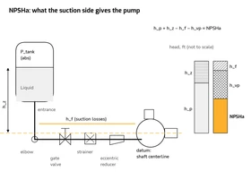
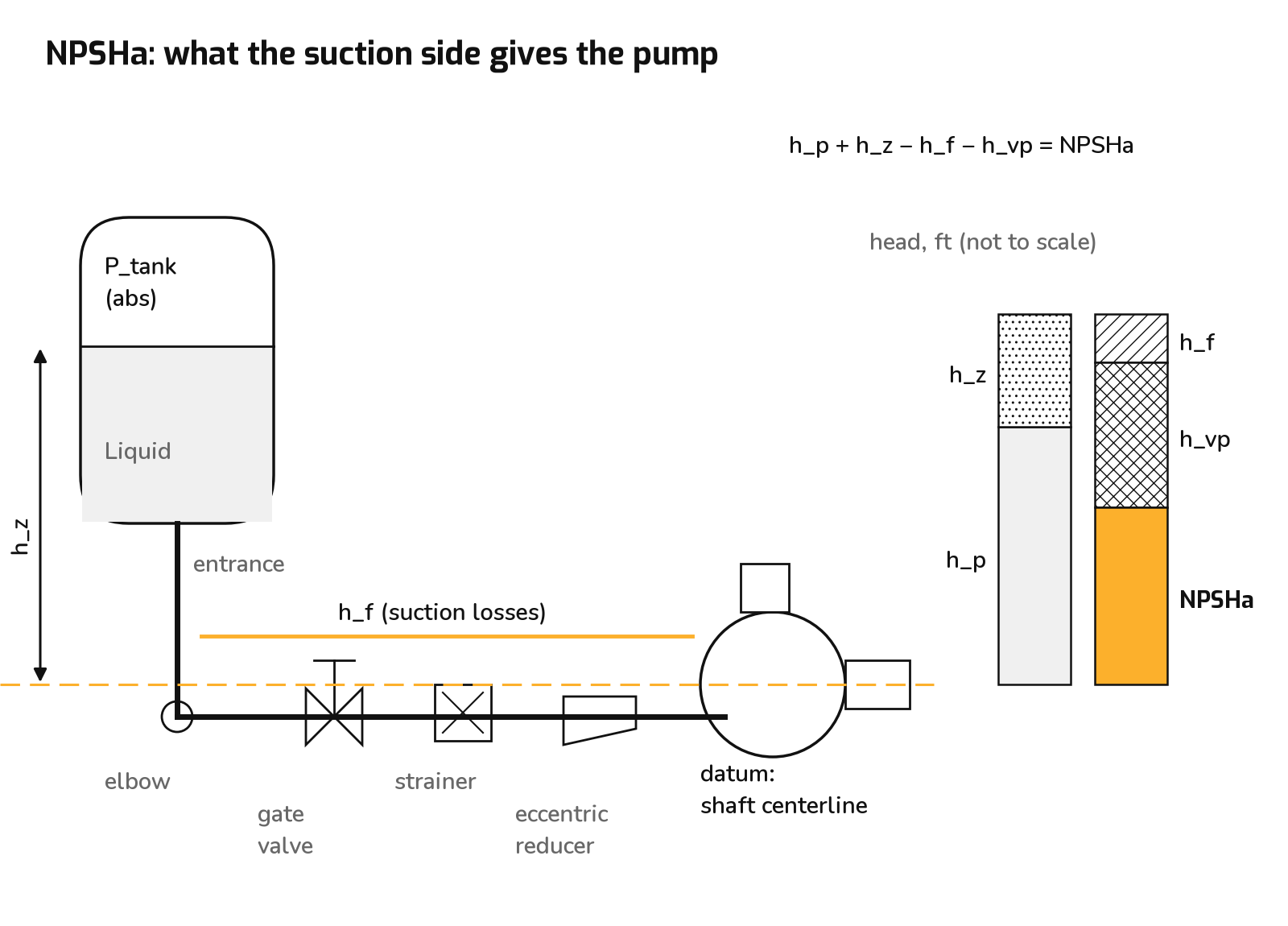
NPSHa is the absolute energy at the pump suction datum, above the liquid's vapor pressure, in feet of the liquid being pumped. For a horizontal end-suction pump the datum is the shaft centerline. With every term in feet of liquid at pumping temperature:
where
- hp = absolute pressure on the liquid surface (atmosphere, or the expansion-tank gas space), ft
- hz = liquid level above (+) or below (−) the datum, ft
- hf = friction loss from the tank outlet to the pump suction flange at rated flow, ft
- hvp = vapor pressure at the pumping temperature, ft
Written in pressure terms, with the free liquid surface in the suction vessel as the reference:
Pressure to head, in US units:
Here 2.309 = 144/62.3637, and SG is referenced to 62.3637 lb/ft³ (saturated water at 60 °F). With SG = ρ/62.3637 the two forms are identical: 2.309/SG ≡ 144/ρ. Two rules apply throughout:
- Use absolute pressure for both hp and hvp.
- Use the density at the pumping temperature.
Solving for the tank pressure needed to reach a target NPSHa:
2.2 What NPSHr actually means: NPSH3
Most published NPSHr curves, centrifugal catalog curves included, are NPSH3 values. ANSI/HI 9.6.1-2017 defines it:
"NPSH3: By Hydraulic Institute definition, the required NPSH of a pump is the NPSH available that will cause the total head (first stage head of multistage pumps) to be reduced by 3%. ... The full published pump head will not, however, be achieved (by definition) when the NPSHA equals the NPSH3 of the pump." ANSI/HI 9.6.1-2017, Section 9.6.1.2, p. 2 [1]
A pump running at NPSHa = NPSH3 is already cavitating hard enough to lose 3 % of its head. NPSH3 marks measurable head breakdown, not the onset of cavitation. HI continues:
"Unless advised otherwise, the user must assume that the published NPSHR is based on the 3% head drop criteria and provide an appropriate margin." ANSI/HI 9.6.1-2017, p. 4 [1]
HI defines margin and margin ratio (2017, p. 2):
The 2024 edition moves the basis from NPSH3 to the manufacturer's NPSHR. The publisher's summary states: "The pump manufacturer's supplied NPSHR value will be greater than or equal to the tested NPSH3 value" [2]. This article treats Dean's printed NPSH as NPSH3, the conservative reading.
The margin tables shown are from ANSI/HI 9.6.1-2017; the 2024 edition applies margins to the manufacturer's NPSHR rather than NPSH3 [2].
2.3 Why margin is needed
From ANSI/HI 9.6.1-2017, pp. 2 and 5–6 [1], paraphrased unless quoted:
- Cavitation starts before the 3 % point. "Some degree of cavitation may exist even when NPSHA is greater than NPSH3 of a pump" (Summary 9.6.1.6, p. 14).
- Uncertainty on both sides. NPSHa depends on friction estimates, tank pressure control and fluid properties. NPSH3 is an average test value, and individual pumps vary.
- Operating range. "Higher or lower rates of flow relative to the shockless entry flow cause a mismatch between the angle of the approaching liquid and the impeller vane inlet tips. The greater the incidence angle, the greater the potential for flow separation and cavitation to occur" (p. 6).
- Duty cycle. "Cavitation damage is time related" (p. 6).
- Material. HI lists cast iron among the least cavitation-resistant common metals (p. 6). The RA impeller is cast iron ("Impeller C.I.", RA IOM materials table, p. 9, item 3 [16]).
2.4 How NPSHr changes with flow
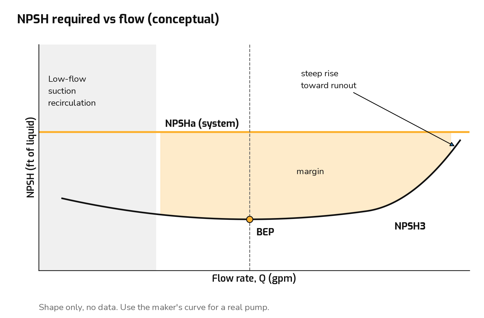
At fixed speed, NPSH3 generally:
- Rises with flow above BEP. Inlet velocity rises, so the dynamic pressure drop from suction flange to vane leading edge rises roughly with V2. Incidence on the vane pressure side worsens. Toward runout the NPSH3 curve usually turns up steeply. The runout end of the curve is where hot systems most often lose margin.
- Rises again at low flow. Below a certain flow the impeller eye develops suction recirculation: reverse flow and vortices at the eye shroud. That causes cavitation and unsteady loads even when NPSHa exceeds the NPSH3 measured at that flow. HI notes that a larger eye "intensifies the effects of suction recirculation", and that low vane overlap can let outlet conditions interact with the inlet, which "can require a higher NPSH margin" (2017, p. 5).
- Has its minimum near BEP. "Most pumps can operate satisfactorily with minimal margin above the NPSH3 value when operating near the best efficiency point (BEP) rate of flow" (p. 2).
Dean adds a thermal reason to avoid low flow:
"DO NOT OPERATE A PUMP AT A LOW FLOW CONDITION, UNLESS PROVISION HAS BEEN MADE TO PREVENT DANGEROUS HEAT BUILD UP WITHIN THE PUMP CASING." Dean RA IOM, p. 19 [16]
In hot water that heat raises the local liquid temperature. Local vapor pressure rises and local NPSHa falls.
2.5 HI margin values
HI 9.6.1-2017 has no category for closed-loop hot water or thermal fluid heat-transfer pumps. The nearest tables, as published [1]:
| HI 2017 table | Pump type | POR margin ratio [minimum margin] | AOR margin ratio [minimum margin] | Page |
|---|---|---|---|---|
| 9.6.1.5.1 | Petroleum/hydrocarbon process, all power | 1.1 [1.0 m (3.3 ft)] | 1.1 [1.0 m (3.3 ft)] | 9 |
| 9.6.1.5.2 | Chemical process, S < 11,000 (US) | 1.1 [0.6 m (2.0 ft)] | 1.1 [0.6 m (2.0 ft)] | 9 |
| 9.6.1.5.2 | Chemical process, S ≥ 11,000 (US) | 1.1 [0.6 m (2.0 ft)] | 1.2 [1.0 m (3.3 ft)] | 9 |
| 9.6.1.5.3 | Boiler feed, < 225 kW (300 hp) per stage | 1.1 | 1.3 | 10 |
| 9.6.1.5.10 | General industrial, all | 1.05 [0.6 m (2.0 ft)] | 1.1 [1.0 m (3.3 ft)] | 14 |
Two HI statements bear directly on hot service:
"Hot water, on the other hand, can act similarly to hydrocarbon liquids. When water is heated to 120-150 °C (250-300 °F), the vapor volume characteristics become similar to that of a typical hydrocarbon." ANSI/HI 9.6.1-2017, 9.6.1.5.3, p. 9 [1]
"NPSH is generally not a concern when designing closed pumping systems. The typical closed system is filled and then pressurized to a 'fill' pressure of 30-70 kPa (4-10 psig). If an inadequate NPSHA condition should occur, it can usually be remedied by increasing the fill pressure." ANSI/HI 9.6.1-2017, 9.6.1.5.7 (building services), p. 12 [1]
The second quote describes HVAC-temperature closed loops. At 250 °F, a 4–10 psig fill is not enough. The water example shows why.
Design target used in this article. This is our engineering choice, based on HI. It is not an HI requirement. We take the larger of a 1.1 ratio or a 3.3 ft margin. That is the hydrocarbon table, which HI says hot water at 250–300 °F resembles, and it matches the general-industrial AOR row. We also show a stricter 1.5 ratio, because the Dean NPSH figure is a single printed label and not a flow-specific curve. The 1.5 is engineering judgment, not an HI value.
2.6 Dean R-series printed NPSH labels
RA and RWA share hydraulics, so the labels below apply to the matching RWA size. The Dean Series RA data pak curve sheets print one NPSH label per curve [15]:
| Size | Printed label | Size | Printed label |
|---|---|---|---|
| 1x1.5x6 RA2096 | 14 FT NPSH | 2x3x10 RA3146 | 15 FT NPSH |
| 1x1.5x8 RA2096 | 14 FT NPSH | 3x4x8.5 | 20 FT NPSH |
| 1x3x8.5 | 7 FT NPSH | 3x4x10 | 14 FT NPSH |
| 1.5x3x6 | 9 FT NPSH | 4x6x8.5 | 20 FT NPSH |
| 1.5x3x8.5 | 10 FT NPSH | 4x6x10 #2 (1750 rpm chart) | 6 FT NPSH |
| 1.5x3x10 | 5 FT NPSH | 4x6x10 #1 RA3186 | 25 FT NPSH |
| 2x3x8.5 RA3146 | 10 FT NPSH |
These are printed labels with no flow printed next to them. Actual NPSHr changes with flow (Section 2.4). For a real selection, use the NPSHr curve at the duty flow and confirm it with the factory. The curve sheets state that performance is for "liquids having a viscosity of 70 SSU or less" and that applications are "subject to confirmation and acceptance by our Engineering Department" [15, curve-sheet disclaimer, pp. 10–22].
About the NPSHr value. Dean's 2x3x8.5 curve sheet prints a single NPSH figure, "10 FT NPSH", with no flow next to it, and does not draw a full NPSHr curve. Both worked examples use that printed 10 ft as a stand-in for the NPSHr at 150 gpm. It is not a measured NPSH3 at our duty flow, and it is not necessarily the worst case on the curve. NPSHr rises with flow, so a pump run farther out on its curve may need more. For a real selection, read NPSHr off the manufacturer's NPSHr curve at your duty flow, or get it from the factory selection, and repeat the margin check. The conclusions in this article don't hinge on the stand-in. With the NPSHa values calculated here, the HI margin target (the larger of 1.1 × NPSHr and NPSHr + 3.3 ft) would still be met even if the true NPSHr at 150 gpm were as high as 114.8 ft for the 250 °F water case, 36.9 ft for Therminol 66 at 0 psig, or 77.9 ft for Syltherm 800 at 66.13 psia.
3. Example inputs
3.1 Fluid properties used in the worked examples
Full property tables, sources and data conventions are in Part 1A, Section 1. The values used here:
- The specific gravity (SG) reference is saturated water at 60 °F, 62.3637 lb/ft³ [3].
- Anything labeled example assumption is a system input chosen for illustration. It is not a property value and not a recommendation for your plant.
Water at 250 °F (RWA service) [3]:
| Property | Value |
|---|---|
| Pv at 250 °F | 29.8440 psia |
| Pv at 260 °F / 270 °F (overshoot checks) | 35.4473 psia / 41.8777 psia |
| Density ρ | 58.8202 lb/ft³ |
| SG | 58.8202 / 62.3637 = 0.9432 |
| Dynamic viscosity μ | 0.229755 cP |
| Kinematic viscosity ν | 0.244 cSt (calculated) |
Thermal fluids at 500 °F / 260 °C (RA service):
| Property at 500 °F | Therminol 66 [4] | Syltherm 800 [5] |
|---|---|---|
| Vapor pressure | 1.73 psia (12.0 kPa) | 41.13 psia (283.6 kPa) |
| Density | 52.5 lb/ft³ (7.01 lb/gal; 840 kg/m³) | 44.62 lb/ft³ (713.96 kg/m³) |
| SG (ref. water 60 °F, 62.3637 lb/ft³) | 0.842 | 0.7155 |
| Dynamic viscosity | 1.28 lb/(ft·h) = 0.529 cP | 0.63 cP |
| Kinematic viscosity | 0.629 cSt | 0.88 cSt (calculated, μ/ρ) |
3.2 The common example suction system
All three worked examples use the same suction piping so the fluids can be compared directly. Every input below is an example assumption unless a source is cited.
| Input | Value | Basis |
|---|---|---|
| Duty | 150 gpm at 230 ft, 7.5 in impeller, 3500 rpm | Point on the shared 2x3x8.5 R-series curve [15] |
| Pump suction nozzle | 3 in | 2x3x8.5 = discharge × suction × impeller; drawing RA-1003 lists 3 in suction, 2 in discharge [15, PDF p. 6] |
| Tank liquid level above pump centerline, hz | +6.0 ft | Example assumption |
| Suction pipe | 4 in Sch 40 steel, ID 4.026 in | Engineering ToolBox Sch 40 table (internal area 12.73 in²) [6] |
| Straight length | 25 ft | Example assumption |
| Fittings | Sharp-edged tank outlet; 2 × 90° LR elbows; 1 full-open gate valve; 1 basket strainer (clean); 4×3 eccentric reducer at the pump flange | Example assumption |
| Roughness ε | 0.00015 ft (0.045 mm) | Engineering ToolBox (commercial steel 0.045–0.09 mm) [7] |
| Atmospheric pressure | 14.696 psia | Standard atmosphere, sea-level example site |
Shared 2x3x8.5 curve, 3500 rpm [15]. Heads were read off the curve drawing to ±3 ft. "Inferred" marks points read where the line was covered.
| Impeller | 50 gpm | 100 gpm | 150 gpm | 200 gpm | 300 gpm |
|---|---|---|---|---|---|
| 8.5 in, head (ft) | 305 | 300 | 294 (inferred) | 287 (inferred) | 266 (inferred) |
| 7.5 in, head (ft) | 238 | 237 | 230 | 221 | 181 (inferred) |
| 6.5 in, head (ft) | 179 | 176 | 168 | 160 | — |
Curve head in feet is the same on every fluid here. Pressure rise and power scale with SG.
Geometry, the same for every fluid:
Fittings, Crane TP-410 method, K = nfT, with fT = 0.017 for 4 in pipe [8][9][10]:
| Item | K basis | K | Source |
|---|---|---|---|
| Tank outlet, sharp-edged | fixed | 0.50 | Crane TP-410 p. A-30, via secondary reproductions [8][9] |
| 2 × 90° LR elbow (r/d = 1.5) | 2 × 14 f_T | 0.476 | Crane TP-410 pp. A-28–A-30, via [8] ([9] lists 16 f_T) |
| Gate valve, full open | 8 f_T | 0.136 | Crane TP-410 p. A-28, via [8][9] |
| Basket strainer, clean | assumed | 1.50 | Example assumption. Use the strainer maker's Cv |
| Sum (4 in velocity head) | 2.612 |
4×3 eccentric reducer, Crane gradual-contraction form referenced to the 3 in (small) end, 30° included angle assumed:
Straight-pipe friction depends on viscosity, so it is computed for each fluid in its own example. Friction factors use Swamee-Jain [11], with the Colebrook value shown for comparison.
Where the K values come from. The fitting losses use the Crane TP-410 method (K = n·f_T). The individual values were taken from published reproductions of the Crane tables [8][9] and cross-checked against each other. They agree on the sharp-edged entrance (0.5) and the gate valve (8 f_T). One lists 14 f_T for the long-radius elbow and the other 16 f_T; the difference is about 0.02 ft here. The reducer uses Crane's gradual-contraction form with an assumed 30° included angle and contributes 0.06 ft. The strainer K of 1.5 is an assumed clean-strainer value; for your system, use the strainer maker's Cv and allow for fouling (Section 6). None of these choices changes a conclusion, because fittings and strainer together are under 1 ft of suction loss.
4. Worked example A: hot water at 250 °F on a Dean RWA4166 2x3x8.5
4.1 Pump
The 2x3x8.5 is an RWA4166 size. It appears in the RWA IOM allowable-piping-load table as RWA4166 2X3X8 1/2, with a 245 lb pump weight [17]. Mechanical limits from the RWA IOM spec page [17, PDF p. 4]:
| RWA4166 item | Value |
|---|---|
| Maximum suction pressure | 260 psig |
| Maximum working pressure | 450 psig, flat from −20 to 400 °F |
| Maximum pumping temperature | 400 °F |
| Flanges | ANSI Class 300 RF |
| Casing | Ductile iron, ASTM A395 |
| Seal | Silicon carbide vs carbon, Aflas elastomers |
Duty: 7.5 in impeller, 150 gpm at about 230 ft. NPSHr: 10 ft, the printed "10 FT NPSH" label on the shared 2x3x8.5 curve sheet (see "About the NPSHr value" in Section 2.6).
4.2 Properties and friction
With μ = 0.229755 cP = 1.5439 × 10⁻⁴ lbm/(ft·s):
4.3 Step 1: NPSH alone (does not govern)
With hp = (Pg + 14.696) × 2.4481, hz = 6.0 ft and hf = 0.93 ft:
| Tank pressure (psig) | hp (ft) | NPSHa (ft) | Ratio to 10 ft NPSHr |
|---|---|---|---|
| 0 (vented: water would boil in the tank) | 35.98 | −32.0 | — |
| 10 | 60.46 | −7.5 | — |
| 15 | 72.70 | +4.7 | 0.47 |
| 20 | 84.94 | +17.0 | 1.70 |
| 25 | 97.18 | +29.2 | 2.92 |
The margin target is the larger of 1.1 × NPSHr or NPSHr + 3.3 ft (Section 2.5). For NPSHr = 10 ft that is 13.3 ft:
A 10 °F overshoot to 260 °F adds 35.4473 − 29.8440 = 5.60 psi, which is 5.60 × 2.4481 = 13.7 ft. Covering it brings the NPSH-only requirement to about 24.1 psig. This is not the design figure. The flashing minimum is much higher, and it governs.
4.4 Step 2: flashing minimum (governs)
On a 250 °F loop the tank pressure is set by flashing, not by NPSH. Part 1A, Section 3.1 derives it. System pressure is held at least 25 psi above saturation at the maximum water temperature, applied at a 60 ft high point (example assumption), which gives Ptank,min = 79.35 psia = 64.66 psig at the tank. The 25 psi margin is a design choice, not a code requirement. The NPSH-only figures above (18.5 psig; 24.1 psig with the 260 °F overshoot) do not govern.
4.5 Step 3: NPSH check at the governing pressure
| Tank pressure | NPSHa (ft) | NPSHr (printed label, ft) | Margin (ft) | Ratio |
|---|---|---|---|---|
| 64.66 psig (79.35 psia), governing minimum | 126.3 | 10 | 116.3 | 12.6 |
That is far above both the 1.1 ratio / 3.3 ft target and the 1.5 ratio. Even if the actual NPSHr at 150 gpm were twice the label (20 ft), the ratio would still be 6.3. On a pressurized hot-water loop, the anti-flash requirement sets the tank pressure, and NPSH becomes a check.
Overshoot. With the tank held at 79.35 psia, a 260 °F excursion cuts the high-point margin from 25 psi to 19.4 psi. Part 1A, Section 3.2 covers re-basing for a higher high-limit.
4.6 Step 4: RWA4166 limits
Converting head to pressure with 2.4481 ft/psi:
| Check | Value | Limit | OK? |
|---|---|---|---|
| Pump suction pressure: 64.66 + (6.0 − 0.93)/2.4481 | 66.7 psig | 260 psig maximum suction | Yes |
| Pump pressure rise at 230 ft: 230/2.4481 | 94.0 psi | ||
| Discharge pressure: 66.7 + 94.0 | 160.7 psig | 450 psig working, to 400 °F | Yes |
| Seal chamber pressure: suction + 0.06 × 230 ft | 66.7 + 5.6 = 72.4 psig |
The RWA IOM states: "Seal chamber pressure equals pump suction pressure plus .06 x developed head" [17, PDF p. 4]. Pressurizing against flashing therefore protects the seal faces as well as the impeller eye (Section 7.2). Size the relief valve and the expansion-tank maximum against the 260 psig suction limit (Part 1A, Section 7.2).
5. Worked examples B and C: thermal oils at 500 °F on a Dean RA3146 2x3x8.5
5.1 Pump
Same shared 2x3x8.5 curve, same duty: 150 gpm at 230 ft on the 7.5 in impeller. NPSHr used: the printed 10 ft label.
Mechanical limits [15][16]: RA3146 maximum working pressure 350 psig, flat from −20 °F to 650 °F (RA IOM Fig. 4, p. 10, read from chart). Maximum suction pressure 100 psig (RA IOM p. 8; data pak p. 2). Maximum pumping temperature 650 °F (data pak p. 2).
Example assumptions: hz = +6.0 ft; suction-leg density taken at 500 °F; friction computed for the same clean suction line at each fluid's 500 °F properties.
5.2 Example B: Therminol 66 at 500 °F
Conversion factor and vapor pressure head. SG = 52.5/62.3637 = 0.8418, shown elsewhere as 0.842:
Friction. TF-8695 lists dynamic viscosity as 1.28 lb/(ft·h), and 1.28/2.419 = 0.529 cP:
NPSHa at a 0 psig blanket (14.696 psia), in pressure form:
NPSHa vs nitrogen-blanket pressure (hz = 6.0 ft, hf = 0.95 ft, NPSHr label 10 ft):
| Blanket (psig) | hp (ft) | NPSHa (ft) | Margin (ft) | Ratio |
|---|---|---|---|---|
| 0 | 40.31 | 40.6 | 30.6 | 4.06 |
| 5 | 54.02 | 54.3 | 44.3 | 5.43 |
| 10 | 67.74 | 68.0 | 58.0 | 6.80 |
| 15 | 81.45 | 81.8 | 71.8 | 8.18 |
| Gas space at P = Pv (theoretical) | 4.75 | 5.05 | −5.0 | 0.50 |
Worked lines, in head form: at 0 psig, (0 + 14.696)(2.7429) + 6.0 − 0.95 − 4.75 = 40.6 ft. At 5 psig, (5 + 14.696)(2.7429) + 6.0 − 0.95 − 4.75 = 54.3 ft.
Blanket pressure needed for the margin target:
At 500 °F, any non-negative blanket pressure meets the NPSH target with wide margin. The nitrogen blanket exists to exclude air and moisture and to control oxidation, not for NPSH. Dean notes that oil makers "will recommend that a nitrogen gas blanket be maintained on the expansion tank of the system" [16, p. 16]. A slight positive blanket also keeps air out. The setpoint is a heater-OEM and fluid-supplier decision.
Overshoot. From the same TF-8695 table [4], tank at 0 psig, hz = 6.0 ft, friction held at the 500 °F value (0.95 ft):
| Bulk temp (°F) | Pv (psia) | ρ (lb/ft³) | NPSHa (ft) |
|---|---|---|---|
| 500 | 1.73 | 52.5 | 40.6 |
| 540 | 2.97 | 51.4 | 37.9 |
| 560 | 3.84 | 50.8 | 35.8 |
| 600 | 6.24 | 49.7 | 29.6 |
Unlike water, a 40 °F excursion costs under 3 ft. The real NPSH risks with thermal oil are elsewhere:
- Light ends from thermal degradation.
- Moisture flashing at start-up. Dean warns that "water residue left in the pump, when exposed to the operating temperature of the system, would create a vapor pressure in excess of the capability of the system to retain it" [16, storage section].
- A hot expansion tank.
Discharge check: with a 0 psig blanket, suction is (6.0 − 0.95)/2.7429 = 1.8 psig. The rise is 230/2.7429 = 83.9 psi, giving 85.7 psig discharge. That is far below 350 psig, and suction is far below the 100 psig limit.
5.3 Example C: Syltherm 800 at 500 °F
Conversion factor and friction. SG = 0.7155 (44.62/62.3637 = 0.71548):
At a low blanket, the fluid boils. With a 17.0 psia blanket (about 2.3 psig), hz = 6.0 ft and hf = 0.96 ft:
| Tank (psig) | NPSHa (ft) |
|---|---|
| 0 | −80.3 |
| 10 | −48.0 |
| 20 | −15.7 |
| 25 | +0.4 |
At a low blanket Syltherm 800 boils in the tank, so the loop must be pressurized. Part 1A, Section 5 sets the tank at Pv + 25 psi = 66.13 psia (51.43 psig). It checks that setting against Dow's 10–15 psi minimum and the aged-fluid vapor pressure, and against the RA3146 limits. At that pressure:
The margin ratio to the 10 ft label is 8.57.
6. Suction piping for hot service
The worked examples show how much the suction line matters. At 150 gpm the clean 4 in line loses 0.93 ft on water, 0.95 ft on Therminol 66 and 0.96 ft on Syltherm 800. The assumed clean strainer alone is more than half of the fittings loss.
Dean's suction piping requirements [16, pp. 12–13; same wording in 17]:
- Line size. No smaller than the pump suction nozzle. Where the line is larger, use an eccentric reducer with the taper on the underside, so no vapor pocket forms at the top.
- Straight run. At least 8 diameters of straight pipe at the suction flange.
- Strainers. Suction screens and strainers "reduce the net positive suction head (NPSH) available" [16, p. 13]. Use the strainer maker's Cv, not an assumed K, and allow for fouling. The examples above assume a clean strainer.
- Support. "Pumps are not constructed to be used as pipe anchors. Both suction and discharge piping must be supported independently of the pumping unit and thermal expansion joints provided..." [16, p. 13].
Further practice for hot service:
- Use hot properties. Compute friction and the pressure-to-head conversion at the pumping temperature.
- Check cold start separately. Therminol 66 is 186 cSt at 60 °F and 70.8 cSt at 80 °F [4]. Cold flow may be laminar, so recompute suction friction for that case.
- Avoid high points in the suction line. Any local high point is a place where vapor or blanket gas collects.
Friction basis and fouling. The suction losses in all three examples (0.93 ft for water, 0.95 ft for Therminol 66, 0.96 ft for Syltherm 800) are calculated for clean pipe and a clean strainer. Strainers load up in service, and new hot-oil and hot-water systems shed scale and debris early on, so allow for it. As a check, we ran a fouled-strainer case with K = 5.0 instead of the clean 1.5. That adds 0.78 ft of suction loss in each case. NPSHa falls from 126.3 to 125.5 ft for the water example, from 40.6 to 39.8 ft for Therminol 66 at 0 psig, and from 85.7 to 84.9 ft for Syltherm 800 at 66.13 psia. The margin ratios against the 10 ft stand-in become 12.6, 4.0 and 8.5. No conclusion changes: flashing, not NPSH, still sets the hot-water tank pressure, and the oil cases keep a wide margin. For your own system, use the strainer maker's pressure-drop data at the dirty-alarm setting, and fit a differential pressure gauge across the strainer so fouling is seen before it costs NPSH.
7. Cavitation vs flashing: what each does to an RA or RWA pump
Cavitation is local. Vapor forms in the low-pressure zone at the impeller eye and collapses a short distance downstream. Flashing is bulk or film vaporization where static pressure falls below vapor pressure: in the tank, at a high point, or across the seal faces. Both starve the pump of liquid. They damage different parts. This section is general centrifugal-pump mechanics unless a Dean source is cited.
7.1 Impeller
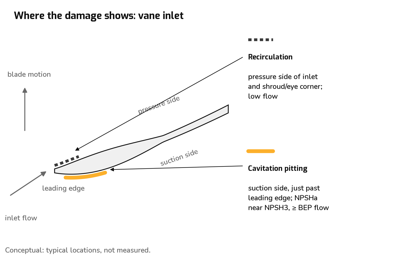
- Where damage appears. Vapor cavities form where local static pressure falls below Pv, usually on the low-pressure (suction) side of the vane just downstream of the leading edge, at the eye. They collapse as they move into higher pressure further down the passage. The result is pitting a short distance into the vane on the suction side, not at the tip. With low-flow suction recirculation, damage tends to show on the pressure side of the vane inlet and at the shroud/eye corner, where the recirculating vortices carry the cavities. Pit location tells you which operating region caused it.
- Erosion pattern. Frosted or sponge-like texture, deepening over time into through-holes in the vane or shroud. Cast iron is among the most damage-prone common metals [1, p. 6], and the RA impeller is cast iron [16, p. 9].
- Loss of head. As vapor volume grows it blocks the inlet passages and the head curve breaks. NPSH3 is the 3 % point on that curve. HI notes choking is worse for cold water than for hydrocarbons or hot water, because "Increases in temperature reduce the vapor-to-liquid-volume ratios, thereby reducing the choking effect", which also reduces collapse energy [1, p. 5]. Hot service is not immune. Damage is less violent per unit of vapor.
- Self-reinforcing geometry change. Eroded leading edges change incidence. NPSH3 rises further and the damage accelerates.
7.2 Mechanical seal
- Vapor at the faces. A mechanical seal runs on a thin liquid film between the faces. If seal-chamber pressure falls toward Pv, or face friction heats the film, the film flashes. The faces lose lubrication and cooling.
- Flashing across the faces. Pressure drops across the face width from seal-chamber pressure to atmosphere. In hot water the liquid flashes partway across the face once local pressure falls below Pv at film temperature. The symptoms are popping, intermittent leakage, and dry running on the outer band.
- Dry running and heat checking. Dry contact spikes face temperature. Hard faces can develop heat checking, radial thermal-fatigue cracks. Carbon faces chip or blister, and elastomers overheat.
- RWA (hot water and glycols). Dean states plainly that hot water flashes at the faces: "The mechanical seal faces are lubricated by the liquid being pumped – it is therefore necessary to have liquid at the mechanical seal faces at all times ... When operating, these liquids may vaporize at the seal faces, this vapor will be removed by the vapor eliminator mounted on the top of the pump" [17, PDF p. 9]. RWA faces are silicon carbide vs carbon with Aflas elastomers [17, PDF p. 4]. Seal-chamber pressure is suction plus 0.06 × developed head (Section 4.6), so suction pressurization sets the floor for seal-face pressure as well as for the impeller eye.
- RA (heat transfer oil). The RA seal stationary is "Silicon Carbide & Viton" [16, p. 9, item 95A]. For RA thermal oil service Dean states: "When pumping at 650°F (343°C), the seal face temperature is 230°F (110°C)" [18, p. 6]. That is a Dean figure for the RA on thermal oil. Do not carry it over to the RWA or to water without factory confirmation. The RWA uses a different seal package and a vapor eliminator.
- Shaft motion. Cavitation-induced vibration and shaft deflection (7.3) open and close the faces dynamically. That adds wear on top of the thermal damage.
- Never run dry. Dean: "A CENTRIFUGAL PUMP MUST NEVER BE RUN WITHOUT LIQUID IN THE CASING. EXTENSIVE DAMAGE MAY RESULT, PARTICULARLY TO THE BEARING OR THE MECHANICAL SEAL. VENT OR FILL THE PUMP SEAL CHAMBER THROUGH THE SEAL VENT CONNECTION TO PROVIDE LUBRICATION TO THE MECHANICAL SEAL FACES" [16, p. 19].
7.3 Bearings
- Vibration. Cavitation produces broadband high-frequency vibration and noise. Suction recirculation produces low-frequency, random, large-amplitude pulsation and radial load. Both reach the bearings.
- Shaft deflection and load. Unequal vapor blockage between impeller passages unbalances the radial hydraulic force. The overhung impeller deflects the shaft and cycles the load on the radial bearing nearest the impeller. Axial thrust also shifts when the pressure field on the shrouds is disturbed, which loads the thrust bearing.
- Product-lubricated radial bearing. On both the RA and RWA, the radial bearing is lubricated by the pumpage [16, p. 16][17, PDF p. 9]. On the RA it is a carbon sleeve: "The radial bearing (180) is lubricated by the liquid being pumped and therefore needs no external lubrication" [16, p. 16], listed as "Radial Sleeve Bearing CARBON" [16, p. 8]. By general tribology (not a Dean statement), a product-lubricated sleeve bearing depends on liquid being present. Vapor in the pumpage threatens its lubrication directly, as well as loading it. The thrust bearings are grease-lubricated angular-contact ball bearings (7308 BG pair on the RA3146) [16, p. 8].
8. Casing thermal growth: centerline vs foot mounting
8.1 Why centerline mounting matters
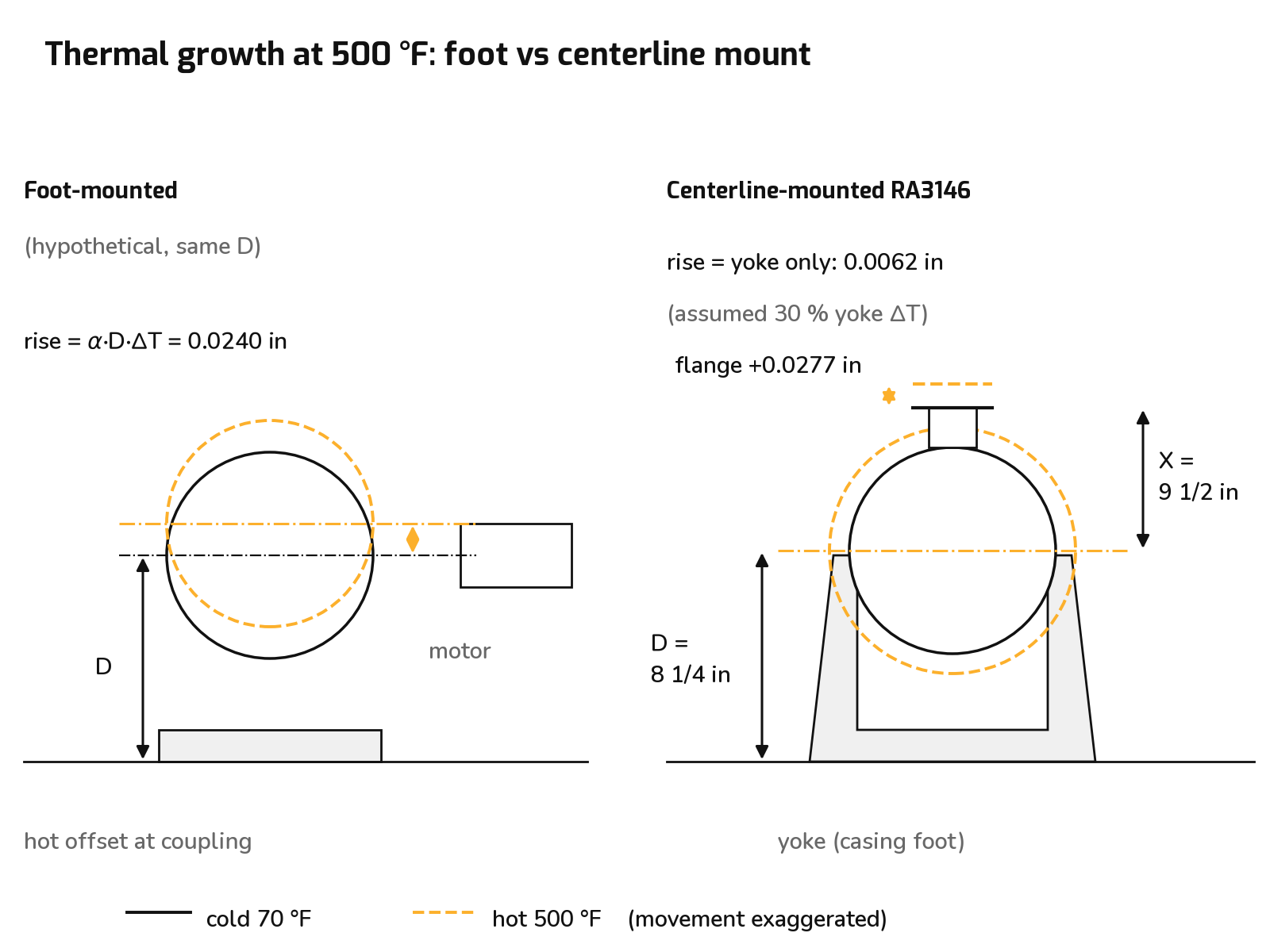
On a foot-mounted casing, the feet are at the bottom of the casing. As the casing heats, everything between the feet and the shaft grows upward. The shaft centerline at the pump end rises by αDΔT. The driver does not rise by the same amount, so the coupling picks up hot offset and angularity that was not there at cold alignment.
On a centerline-mounted casing, the support lugs lie in the horizontal plane of the shaft centerline. Casing growth splits up and down about that plane, so casing growth does not move the centerline. The only rise comes from the support underneath (yoke or pedestal), which runs much cooler than the wetted casing.
RA3146. Dimension drawing RA-1003 ("RA-3146 with shaft fan") shows the casing bolted at its horizontal centerline to a U-shaped yoke [15, PDF p. 6]. Dimension D runs from the yoke base to the shaft centerline. The parts list calls the yoke the casing foot (item 56, cast iron) [16, p. 9]. Dean:
"Centerline mounted pump casing support allows thermal expansion of the casing about the pump centerline without disturbing shaft alignment" Dean R Series High Temperature Bulletin C 1.4.45, p. 2 [18]
RWA. The RWA4166 also uses a cast-iron casing foot (item 56) [17, PDF p. 4]. The RWA2096 has no casing foot ("N.A.") and is a foot-mounted version.
Which pump the numbers describe. The thermal-growth example in this section is worked for the Dean RA3146 2x3x8.5, using dimensions from Dean dimension drawing RA-1003: shaft centerline D = 8¼ in above the yoke base, and discharge flange face X = 9½ in above the centerline. The same method applies to the RWA4166 hot-water pump. Its casing also bolts to a cast-iron casing foot (item 56). Substitute your pump's own D and X from its dimension drawing, and the casing temperature rise for your service. The 250 °F columns below show what the method gives at hot-water temperatures using the same 8¼ in height.
8.2 Casing material and α
- Material. Casing (item 5) is "D.I. (10)", where note (10) = "Ductile Iron – ASTM A395", in both the RA IOM [16, p. 9] and the RWA IOM [17, PDF p. 4]. ASTM A395: "For temperatures above 450°F and up to 650°F, only Grade 60–40–18 castings are suitable" [13]. At 500 °F the RA casing is therefore 60-40-18. The RWA grade at 250 °F is not stated.
- α, ferritic ductile iron 60-40-18 (MatWeb, Dura-Bar 60-40-18, mean from 21 °C) [12]: 11.5 µm/m·°C over 21–100 °C, which is 6.39 × 10⁻⁶ /°F; 12.2 µm/m·°C over 21–300 °C (70–572 °F, covering 500 °F), which is 6.78 × 10⁻⁶ /°F. These are bar-stock values applied to castings.
- Cast-iron yoke and steel frames: 5.8 × 10⁻⁶ /°F for cast iron and 6.5 × 10⁻⁶ /°F for steel [14].
8.3 Worked example: RA3146 2x3x8.5 at 500 °F
From drawing RA-1003, size 2x3x8.5 [15, PDF p. 6]:
| Dimension | Value | Meaning |
|---|---|---|
| D | 8 1/4 in | Yoke (casing foot) base to shaft centerline |
| X | 9 1/2 in | Shaft centerline to discharge flange face |
| Suction / discharge | 3 in / 2 in, ANSI Class 300 RF |
Example assumptions: cold alignment at 70 °F; pumping temperature 500 °F, so ΔT = 430 °F; casing metal conservatively taken at the pumping temperature; yoke metal averages 30 % of the casing temperature rise. The 30 % figure is an unsourced assumption, not Dean data. Measure it on a running unit.
Hypothetical foot-mounted casing with the same D:
Actual centerline-mounted RA3146: casing growth contributes 0 at the centerline. The cast-iron yoke grows over its height D:
Discharge flange. Centerline mounting does not stop the nozzle moving relative to the shaft. The flange face is X = 9.5 in above the centerline:
On a foot-mounted casing the flange would rise (6.78 × 10⁻⁶)(8.25 + 9.5)(430) = 0.0517 in relative to the base. On the centerline-mounted RA3146 it rises about 0.028 in relative to the centerline, plus the 0.006 in of yoke rise. Either way, the discharge piping must take the movement through its supports and expansion provisions. It must not push back on the nozzle.
| Item (RA3146 2x3x8.5, 500 °F) | Rise (in) | Basis |
|---|---|---|
| Shaft centerline, foot-mounted (hypothetical) | 0.0240 | α_DI · D · ΔT |
| Shaft centerline, centerline-mounted (actual) | 0.0062 | α_CI · D · 0.3ΔT (assumed yoke at 30 % of ΔT) |
| Discharge flange relative to the centerline | 0.0277 | α_DI · X · ΔT |
| Discharge flange relative to the base, foot-mounted (hypothetical) | 0.0517 | α_DI · (D+X) · ΔT |
| Dean alignment target | 0.002 TIR | RA IOM p. 13 [16] |
A rim indicator reads TIR = 2 × offset. The hypothetical foot-mounted rise of 0.024 in would read about 0.048 in TIR, 24 times Dean's 0.002 in target. Even the centerline-mounted case, about 0.012 in TIR at the assumed 30 %, exceeds the target once the support grows. That is why Dean requires a hot alignment check (Section 8.5).
8.4 Sensitivity to the assumed yoke temperature
The centerline-mounted result depends directly on the yoke temperature assumption. Rise = αCI D (fraction × ΔT), with αCI = 5.8 × 10⁻⁶ /°F and D = 8.25 in. The 250 °F column applies the same 8.25 in height at hot-water temperature.
| Yoke temperature rise, % of casing ΔT (assumption) | RA3146, 500 °F oil (ΔT 430 °F): CL rise, in (TIR) | RWA, 250 °F water (ΔT 180 °F): CL rise, in (TIR) |
|---|---|---|
| 0 % (yoke stays at ambient) | 0.0000 (0.000) | 0.0000 (0.000) |
| 30 % (value used above) | 0.0062 (0.012) | 0.0026 (0.005) |
| 50 % | 0.0103 (0.021) | 0.0043 (0.009) |
| For comparison: foot-mounted casing (100 % of ΔT, ductile iron) | 0.0240 (0.048) | 0.0095 (0.019) |
Centerline mounting still beats foot mounting at 50 %: 0.0103 vs 0.0240 in at 500 °F. The "about 4 times less" comparison applies only if the yoke runs at 30 % of the casing rise; at 50 % it is about 2.3 times. The hot rise exceeds the 0.002 in TIR target once the yoke rise is above about 5 % of the casing rise at 500 °F, or about 12 % at 250 °F. That is another reason to check alignment hot.
Water case (RWA, 250 °F, ΔT = 180 °F), per inch of support height: (6.39 × 10⁻⁶)(180) = 0.00115 in/in. At the same 8.25 in height: foot-mounted 0.0095 in; centerline yoke at 30 % ΔT, (5.8 × 10⁻⁶)(8.25)(54) = 0.0026 in.
What this means in practice. The table above is the result to use; the 30 % row is only one illustrative point. How hot the yoke or pedestal runs depends on the installation: casing temperature, pump size, fan cooling, insulation, airflow around the baseplate and how long the pump has been at temperature. We found no published figure for it in Dean's literature or in API 610 and its IOGP supplement. The supplement's requirement for guides or key slots at the support pedestals of centerline-supported pumps above 500 °F (260 °C) shows the support itself is expected to move. Dean also offers a water-cooled pedestal for severe service. So measure the support temperature on a running pump, at the yoke or pedestal close to the casing lugs, and read the rise from the table. Centerline mounting beats foot mounting at every fraction in the table. The size of the advantage depends on the support temperature: about 4 times less rise at 30 %, about 2.3 times at 50 %, and no centerline rise at all if the support stays at ambient. The expansion coefficients are mean values from published ductile- and cast-iron data. At 250 °F the ductile-iron value is taken from the 70–212 °F range, a small extrapolation that doesn't affect the comparison.
8.5 Coupling, nozzle loads and hot alignment
- Coupling. If only the pump side rises, the coupling sees parallel offset plus some angularity across the spacer. Dean: "Failure to properly align the unit will result in vibration, short bearing life, and reduced mechanical seal life" [16, p. 13].
- Nozzle loads. Allowable nozzle loads are tabulated in each IOM. The RWA IOM table "Allowable Piping Loads for RWA2096, RWA4166 and RWA4206" lists the RWA4166 2x3x8.5 at M_X 690, M_Y 340, M_Z 725 lb·ft [17].
- Axial growth. Shaft and casing growth also change the coupling gap (DBSE). Check it against the coupling maker's allowance.
The bearing frame and motor still grow. Centerline mounting removes only the casing term. The bearing housing foot (item 9, steel) [16, pp. 9, 25] and the motor frame also warm.
Example assumptions: bearing-foot height equal to D (8.25 in) at ΔT = 60 °F; motor shaft height equal to the pump shaft height D (8.25 in), because the coupled shafts share one centerline, at ΔT = 40 °F. The actual motor frame height (NEMA D) and shim or pedestal stack depend on the motor. Measure these temperatures.
Motor height. The example uses a motor shaft height of 8.25 in, matching the pump shaft centerline; use your motor's actual shaft height. Use your motor's actual frame temperature rise too; the 40 °F rise used here is also an example value. Either way the motor term is small, about 0.002 in, but it can be comparable to the 0.002 in alignment target, which is one more reason to finish alignment hot.
At these assumed temperatures, the pump bearing end rises 0.0032 in and the motor 0.0021 in. The two partly cancel, leaving about 0.001 in of net rise at that end, plus the centerline rise on the casing side. The actual net offset depends on measured frame temperatures.
Dean is explicit about hot alignment [16, pp. 12–13, 18], and the RWA IOM carries the same wording [17]:
- "No allowance for thermal expansion is made for motor driven units in mounting the driver."
- "Final alignment must always be checked and corrected at the operating temperatures of the pump and driver."
- "The pump and driver alignment must again be checked at the operating temperature and alignment corrected under the hot condition."
- Warm up gradually: "A centrifugal pump should never be started until all the parts are up to the temperature of the liquid to be pumped."
9. Takeaways
- Match the pump to the fluid. Hot water and glycols: Dean RWA. Heat transfer oils: Dean RA. Use the shared R-series curve for the size.
- Convert pressure to head with hot density, using absolute pressures: h = 2.309 P/SG = 144 P/ρ.
- Compute suction friction from the actual line at rated flow. Use the strainer maker's Cv. Allow for fouling.
- Calculate NPSHa = hp + hz − hf − hvp.
- Get NPSHr (NPSH3) at the duty flow from the factory curve, not a single printed label. Check the operating range against runout and low-flow recirculation.
- Apply a margin. HI 9.6.1 gives no hot-water or thermal-fluid category. This article uses the larger of 1.1 × NPSH3 or NPSH3 + 3.3 ft, with 1.5 shown as a stricter case.
- Check pump limits: maximum suction pressure (RWA4166 260 psig, RA3146 100 psig), working pressure at temperature (RWA4166 450 psig to 400 °F, RA3146 350 psig to 650 °F), and seal-chamber pressure (RWA: suction + 0.06 × developed head).
- Lay out the suction line: no smaller than the nozzle, eccentric reducer flat on top, at least 8 diameters straight at the flange, no high points.
- Support piping independently and provide for thermal expansion. Keep nozzle loads within the IOM table.
- Align cold, then check and correct alignment hot. Centerline mounting removes the casing term. The yoke, bearing frame and motor still grow.
For NPSH checks, pressurization and Dean RA or RWA selection, use HydroSuite Pro, or call 888-341-7085 / email sales@pumpresource.us.
Read Part 1A: Part 1A: pressurization and expansion covers vapor pressure basics, anti-flash pressurization for the RWA hot-water loop, the N₂ blanket, the Syltherm 800 case including aged vapor pressure, and expansion tank sizing.
References
Standards and public data
- Hydraulic Institute, ANSI/HI 9.6.1-2017 Rotodynamic Pumps Guideline for NPSH Margin. Public copy incorporated by reference: https://law.resource.org/pub/us/cfr/ibr/inc/ansi/ansi.hi.9.6.1.2017.pdf
- Hydraulic Institute, HI 9.6.1-2024, publisher summary of changes: https://store.accuristech.com/standards/hi-9-6-1-2024?product_id=2926885
- NIST Chemistry WebBook, SRD 69, Thermophysical Properties of Fluid Systems, water saturation tables. 250–270 °F: https://webbook.nist.gov/cgi/fluid.cgi?Action=Data&Wide=on&ID=C7732185&Type=SatP&Digits=6&THigh=270&TLow=250&TInc=10&RefState=DEF&TUnit=F&PUnit=psia&DUnit=lbm%2Fft3&HUnit=Btu%2Flbm&WUnit=ft%2Fs&VisUnit=cP&STUnit=lb%2Fin ; 60 °F: https://webbook.nist.gov/cgi/fluid.cgi?Action=Data&Wide=on&ID=C7732185&Type=SatP&Digits=6&THigh=60&TLow=60&TInc=10&RefState=DEF&TUnit=F&PUnit=psia&DUnit=lbm%2Fft3&HUnit=Btu%2Flbm&WUnit=ft%2Fs&VisUnit=cP&STUnit=lb%2Fin
- Eastman, Therminol 66 Heat Transfer Fluid, Technical Bulletin TF-8695, liquid property tables: https://www.eastman.com/content/dam/eastman/corporate/en/literature/t/tf8695a.pdf ; datasheet: https://productcatalog.eastman.com/tds/ProdDatasheet.aspx?pn=Therminol+66+heat+transfer+fluid&product=71093438
- Dow, SYLTHERM 800 Heat Transfer Fluid: Product Technical Data, Form No. 176-01435-1097 (Oct. 1997), Table 4/5 saturated liquid properties and design sections; Fig. 7 on printed p. 18; fluid analysis and annual sampling on printed p. 11 (distributor-hosted copy): https://cms.chempoint.com/getmedia/ca6e00a4-1e13-4412-b5ce-d58e04a1562f/Syltherm800Brochure.pdf.aspx
- Engineering ToolBox, ANSI Schedule 40 Steel Pipe Dimensions: https://www.engineeringtoolbox.com/ansi-steel-pipes-d_305.html
- Engineering ToolBox, Surface Roughness Coefficients: https://www.engineeringtoolbox.com/surface-roughness-ventilation-ducts-d_209.html
- PipingCalcPro, Fitting Loss Coefficients (Crane TP-410 reproduction, pp. A-28–A-30): https://piping.xcalcpro.com/pipedata/fitting-loss-coefficients
- SimuPipe, Pipe Fitting K-Factor Table (Crane TP-410) (secondary reproduction): https://simupipe.com/resources/k-factor-table
- Crane Co., Technical Paper No. 410, Flow of Fluids Through Valves, Fittings, and Pipe. Standard bibliographic citation; the K values used here are as reproduced in [8][9].
- Swamee, P. K., and Jain, A. K. (1976), "Explicit equations for pipe-flow problems," Journal of the Hydraulics Division, ASCE, 102(HY5), 657–664. Standard bibliographic citation.
- MatWeb, Dura-Bar 60-40-18 Continuously Cast Ductile Iron Bar Stock: https://www.matweb.com/search/datasheet_print.aspx?matguid=5fd2321bcd464c19892c1acd09dabde8&n=1
- ASTM A395/A395M, scope: https://store.astm.org/a0395_a0395m-99r14.html
- EBAA Iron, Expansion Length Calculator (coefficient table): https://ebaa.com/expansion-calculator/
Dean literature
- Met-Pro / Dean Pump, Dean Pump Series RA data pak: spec page p. 2; dimension drawing RA-1003 (RA-3146 with shaft fan), PDF p. 6; curve sheets pp. 10–22.
- Tusk Industrial, Dean RA Series Installation, Operation and Maintenance Manual, document TUSK-IOM-DEAN-RA-001 v1.0 (distributor-hosted copy, file Dean-RA-Series-IOM.pdf; page numbers refer to this copy): pp. 8, 9, 10 (Figure 4), 12, 13, 16, 18, 19, 25; storage section.
- Tusk Industrial, Dean RWA Installation, Operation and Maintenance Manual (distributor-hosted copy; page numbers refer to this copy): spec page and pressure–temperature chart, PDF p. 4; lubrication and seal, PDF p. 9; allowable piping loads table; piping and alignment section.
- Dean Pump, R Series High Temperature Pumps Bulletin C 1.4.45, pp. 2, 6.